MCM : A New Technology in Predictive Maintenance
|
| Plant Maintenance Resource Center
MCM : A New Technology in Predictive Maintenance
| |
|
|
|
|
MCM : A New Technology in Predictive MaintenanceBy Burak Gökmen, Vasfi Eldem, Anthony James Wetherilt, Ahmet Duyar
AbstractMCM (Motor Condition Monitor) is a device that has the capability of detecting impending mechanical and electrical failures in motors and motor based systems at the early stages of fault development. The experimental modelling technology used in MCM can automate fault detection and prevent unplanned machine failures. The paper describes the technology and presents the results of experiments that were done to prove the capability of the MCM device in fault detection. IntroductionTraditional failure prediction systems such as vibration based systems, often do not go beyond providing the measurements and tools to analyse and trend those measurements. The influence of external factors like external vibrations, the exact location of the measurements further complicate the issue. The expert systems that are used in large plants have their own limitations. They require an extended training period for the database to be built up, in order to work reliably. In addition, as time passes the database often will need to be updated as new incidents occur. False alarms can become serious headaches with these systems. On the other hand, measurement of electrical signals such as voltage and currrent is much more reliable and easy, and the effects of several faults on stator current are well-known([1],[2]). Mechanical faults such as air gap eccentricities, misalignment and ball bearing defects affect the permeance and electrical faults such as broken rotor bars have an effect on magnetomotive force. These quantities are directly related with stator currents. The experimental modelling technology that Artesis has used for failure prediction([3]-[7]) relies on this concept and provides an objective overall assessment of the motor, without requiring any long training cycles or trending analysis. Three phase voltages and currents are the only measurements used by the technology, and hence, the technology is immune to external influences, especially to vibration. In the sequel, after a general description of MCM device and the underlying technology, the results of several mechanical and electrical fault experiments are presented. Possible benefits of using MCM are described. A detailed product implementation of MCM can be found in [8]. II-General Description of MCM DeviceMCM utilises model based fault detection and diagnosis methodology for early fault prediction in electric motors. The basic principal of this approach is to compare the dynamic behaviour of the actual motor with its mathematical model. The model consists of a set of differential equations, which describe the electromechanical behaviour of the motor. MCM uses real-time data obtained from the motor and processes it with a set of system identification algorithms, which yield the parameters of the mathematical model. MCM is manufactured as a small( 9 x 9 x 19.5 cm), box-shaped device, that is suitable for installation on motor control panels (Figures 1&2). It provides five different warning levels for initiating diagnostic checks, scheduling maintenance or an emergency stop. The LCD screen shows the physical quantities such as rms-values of three phase voltage and current signals, power, powerfactor as secondary outputs. The device uses the motor supply voltage and current as its only inputs. The current sensors are attached separately, depending on the power of the motor to be monitored. MCM's hardware include a RISC processor with onboard A/D converter and RAMs. Its memory requirement is 2Mbytes(DRAM) and 4 Mbits(Serial Flash). It contains an RS-485 serial I/O port for data transmission. In addition to these features, MCM is also available as a flexible 'system-on-chip' application, a factory programmed electronic chip that can be integrated directly into the circuit of a drive or motor itself. This OEM solution, delivered together with a product development kit, allows creation of intelligent drives, motors and motor based systems that detect their own faults before failures occur, within a minimum time-to-market period.
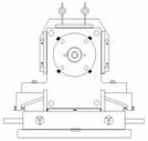
In testing mode, it is also possible to update the model obtained in the learning mode by using the new incoming data. III-Experimental SetupThe most common types of machine problems in industry are misalignment and balancing, which can lead to premature bearing, coupling, shaft seal and gear wear. Other common problems include electrical insulation deterioration or shorting, loose or worn electrical connections and inadequate lubrication ([9]). With this trending in mind, the focus was on misalignment and unbalance faults during the mechanical fault experiments. Misalignment or static eccentricity is defined as a stationary minimum air gap, while unbalance or dynamic eccentricity is defined as a rotating air gap ([2]). For electrical faults, attention was given to stator and rotor related insulation and connection problems. The experiments presented in the next section were done using a specially designed fault simulator whose front-end view is shown in Figure 3. The power of the fault simulator is 1.1 kW. This fault simulator enables simulating both electrical and mechanical faults easily. Its stator has a special winding that has several leads at different points on it. It is possible to have different levels of stator short circuit by connecting different leads.
The fault simulator has four gauges on top of it which show the position of the rotor in the air gap. It is possible to move the part of the fault simulator, in which the bearing housing resides, up and down by adjusting the position of screws in the bottom. Therefore, static eccentricity is created by tilting the rotor from both ends or only one end. In case of no static eccentricity, the distance between the rotor and stator surfaces, i.e. the length of air gap, is 0.25 mm. Dynamic eccentricity, on the other hand, is created by mounting a weight to a flywheel connected to the rotor. IV-Results Of ExperimentsMCM has been tested exhaustively under laboratory conditions. The experiments presented in this section demonstrate the ability of MCM in detecting electrical and mechanical faults.
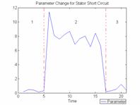
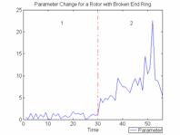
The effect of the first electrical fault experiment, stator short circuit, on one of estimated parameters is illustrated in Figure 4. In Regions 1&3, the stator winding is not short-circuited. The resistance of the winding in this case is 8.0 Ohm. However, in Region 2 short circuit is applied to the winding such that its resistance decreases to 7.8 Ohm. Figure 5 shows the graph corresponding to the broken end ring experiment. The fault simulator runs under variable load conditions in this experiment. Region 1 corresponds to the case where there is no fault. However, in Region 2, the original rotor is changed with the rotor with a broken end ring.
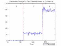
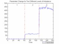
The effect of the first mechanical fault experiment, static eccentricity with two different levels, on one of the estimated parameters is illustrated in Figure 6. The motor operates under normal conditions in Region 1, no fault is applied to the motor. Load is constant. In Region 2 one-sided eccentricity is applied to the motor with a rotor tilt of 0.2mm from only one end. In Region 3 two-sided eccentricity is applied to the motor with a rotor tilt of 0.2mm from both ends. Figure 7 illustrates the results of dynamic eccentricity experiment. The motor runs under constant load in this experiment. In Region 1, there is no fault introduced to the motor. However, in Region 2 imbalance, therefore dynamic eccentricity, is applied to the system by mounting an object to the flywheel. The weight of the object mounted on the flywheel is about 2.5% of the flywheel's weight. In Region 3, the weight of the object is increased a little more so that it is about 3.5% of the flywheel's weight.
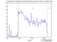
The faulty bearing experiment, depicted in Figure 8, was done by replacing the original bearing with a faulty one that has a 1 mm(diameter) hole on its outer ring. This test was done under constant load conditions. In Region 1, the bearing is the one that has no faults. In Region 2, it is replaced by the faulty bearing and in Region 3 the original bearing is again mounted to the rotor. It is evident from these figures that parameters calculated are quite sensitive to the faults introduced to the system. When the fault is applied to the motor, the parameters increase which means a significant change in the motor with respect to the motor model obtained in the learning mode. V-Potential Benefits of Using MCMMCM is developed with predictive maintenance in mind. Its menu is easy to use, the simple and reliable warnings that MCM generates and the diagnostic information it provides are aimed at simplifying the job of the predictive maintenance professionals and increasing the uptime performance.
The monitoring of MCM units installed at several different locations in a plant is easy because of the network feature of MCM. The monitoring service is provided by networking the MCM units to a central monitoring station. Hence, all MCM units can be monitored and commanded remotely from a central PC, which is a distinct advantage. VI-ConclusionsThe results obtained from the exhaustive tests in laboratory conditions prove the capability of MCM in detecting both mechanical and electrical faults in motor based systems. Thus experimental modelling technology provides an effective and much simpler means of failure prediction in electric motors than traditional methods. The technique relies on measuring three phase voltage and current signals and provides an overall assessment of the motor. The assessment consists of the comparison of the model parameters obtained during test mode with the motor model obtained in the learning mode. Once the deviation exceeds a certain threshold, a relevant warning message on the display is reported to the user. Therefore, MCM's experimental modelling technology will replace the arbitrary time intervals with maintenance scheduled only when the condition of the equipment requires it. This will reduce the frequency and cost of unplanned machine failures.References[1] T.G. Habetler, "Motor Condition Monitoring Tutorial," IEEE IAS Annual Meeting, 1995. [2] M. Xu and T. Alford, "Motor Current Analysis and Its Application in Induction Motor Fault Analysis," Predictive Maintenance Technology National Conference, 1997. [3] A. Duyar and W. C. Merrill, "Fault Diagnosis For the Space Shuttle Main Engine," AIAA Journal of Guidance, Control and Dynamics, vol. 15, no. 2, pp. 384-389, 1992. [4] A. Duyar, V. Eldem, W. C. Merrill, and T. Guo, "Fault Detection and Diagnosis in Propulsion Systems: A Fault Parameter Estimation Approach," AIAA Journal of Guidance, Control and Dynamics, vol. 17, no. 1, pp. 104-108, 1994. [5] J. Litt, M. Kurtkaya, and A. Duyar, "Sensor Fault Detection and Diagnosis of the T700 Turboshaft Engine," AIAA Journal of Guidance, Control and Dynamics, vol. 187, no. 3, pp. 640-642, 1995. [6] J. L. Musgrave, T. Guo, E. Wong, and A. Duyar, "Real-Time Accommodation of Actuator Faults on a Reusable Rocket Engine," IEEE Trans. Cont. Syst. Technol., vol. 5, no. 1, pp. 100-109, Jan. 1997. [7] V. Eldem and A. Duyar, "Parametrization of Multivariable Systems Using Output Injections; Alpha Canonical Form," Automatica, vol. 29, no. 4, pp. 1127-1131, 1993. [8] D. Eroglu, M. K. Göbülük, M. Gencer, and S. Parmaksiz, "New Technology in Electric Motor Failure Prediction," Control Engineering Magazine, August 2000. [9] "An Introduction to Condition Based Maintenance(CBM)," Predictive Maintenance Technology National Conference, 1997.
Copyright 1996-2009, The Plant Maintenance Resource Center . All Rights Reserved.
|